This week, we had to model a notched piece, which was shown in class, through user parameters or variables into a pattern that would be used for laser cutting. Although I have prior knowledge in CAD software (Onshape) using it to create different assemblies, I have never used variables and barely used linear patterns that much. So to strengthen my knowledge, I searched up and read these links to learn more on variables and linear patterns.
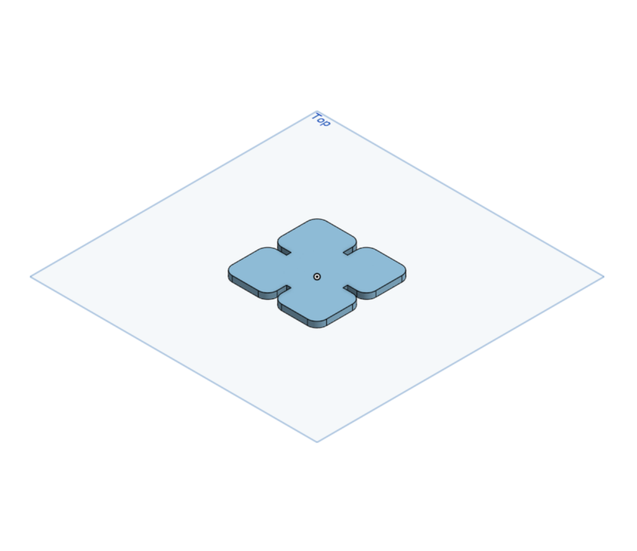
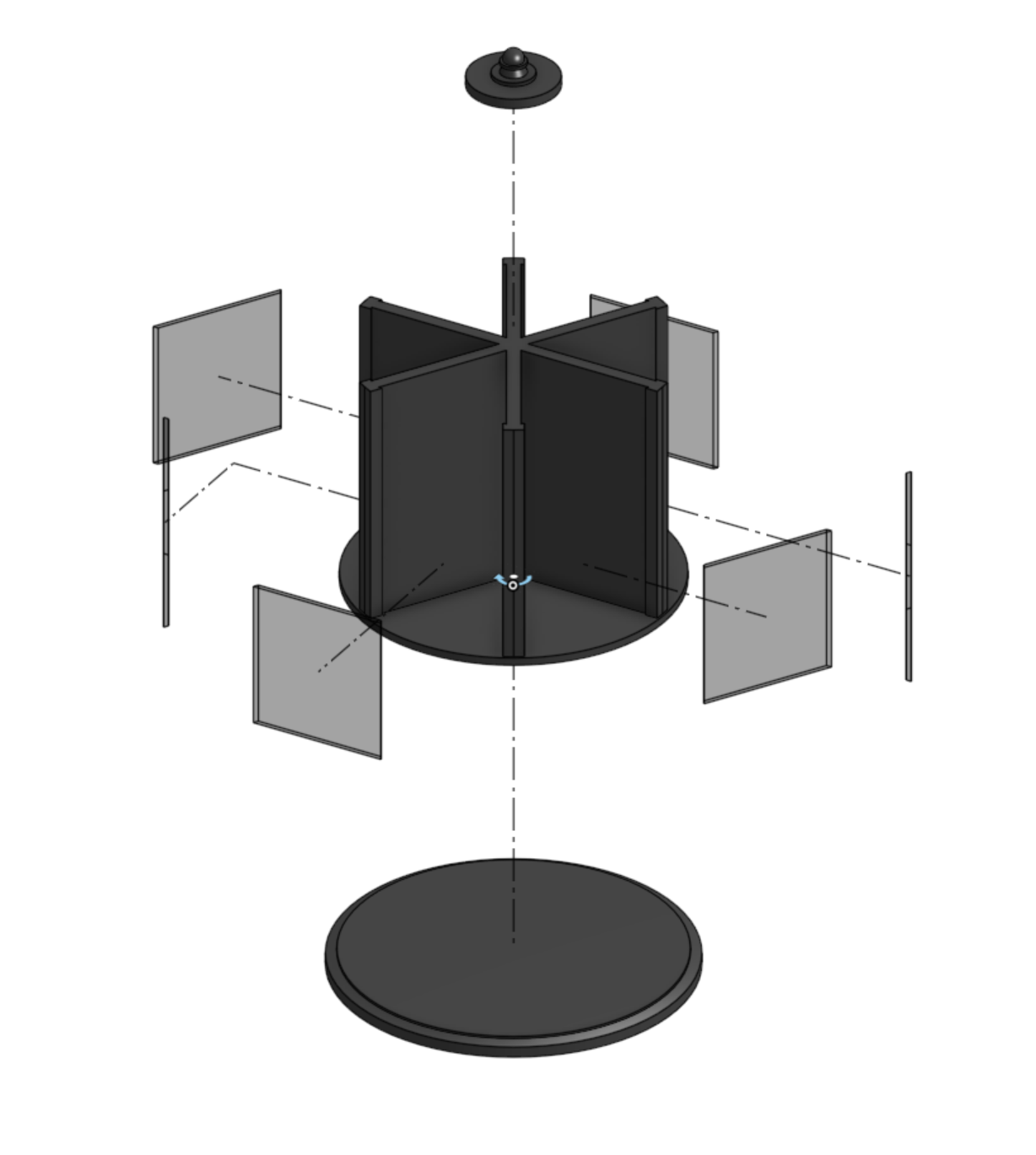
For the assignment, I chose to model my spinning desktop organizer. So, I measured and split the design into 4 different segments: the base, the transparent panels, the spinning part/structure, and the top (the knob that is used to spin the desktop organizer).
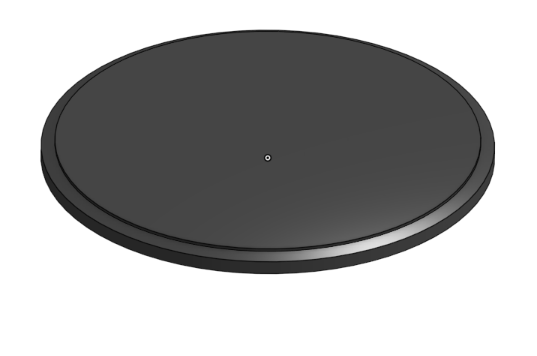
On the base, I started with a circle sketch, extruded it, offset a plane for another sketch to form a loft and then create a third sketch from the loft for an extrude.
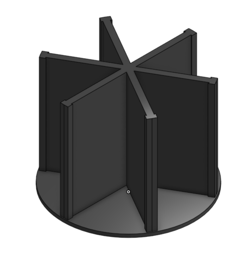
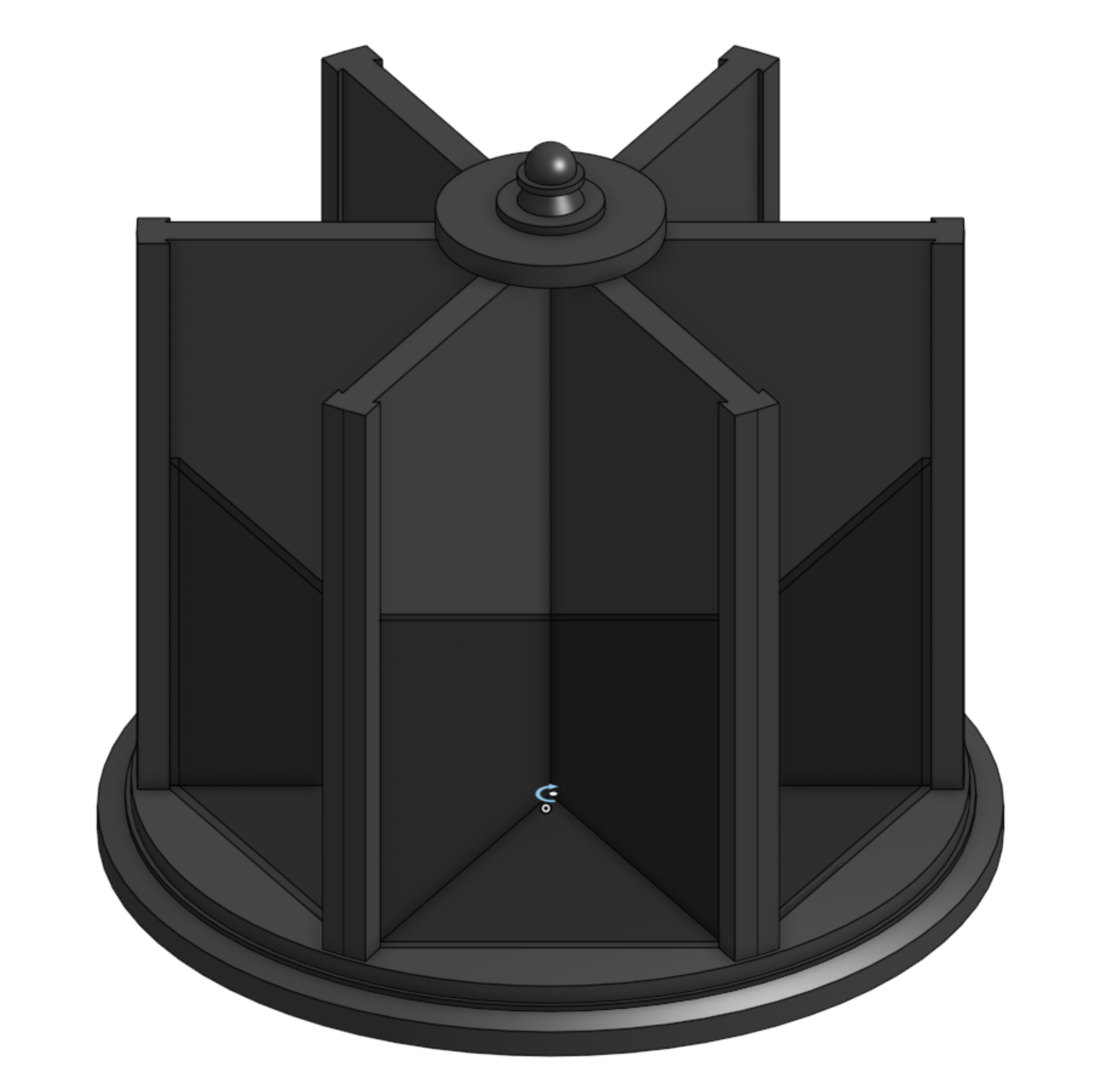
Next came the structure of the model, I started with a circle sketch, extruded it, offset another circle to make sure that none of the edges of the ridges for the structure were going to touch outside of the circle. After that I modeled the dividers with a hexagon shape and series of sketches to then extrude it.
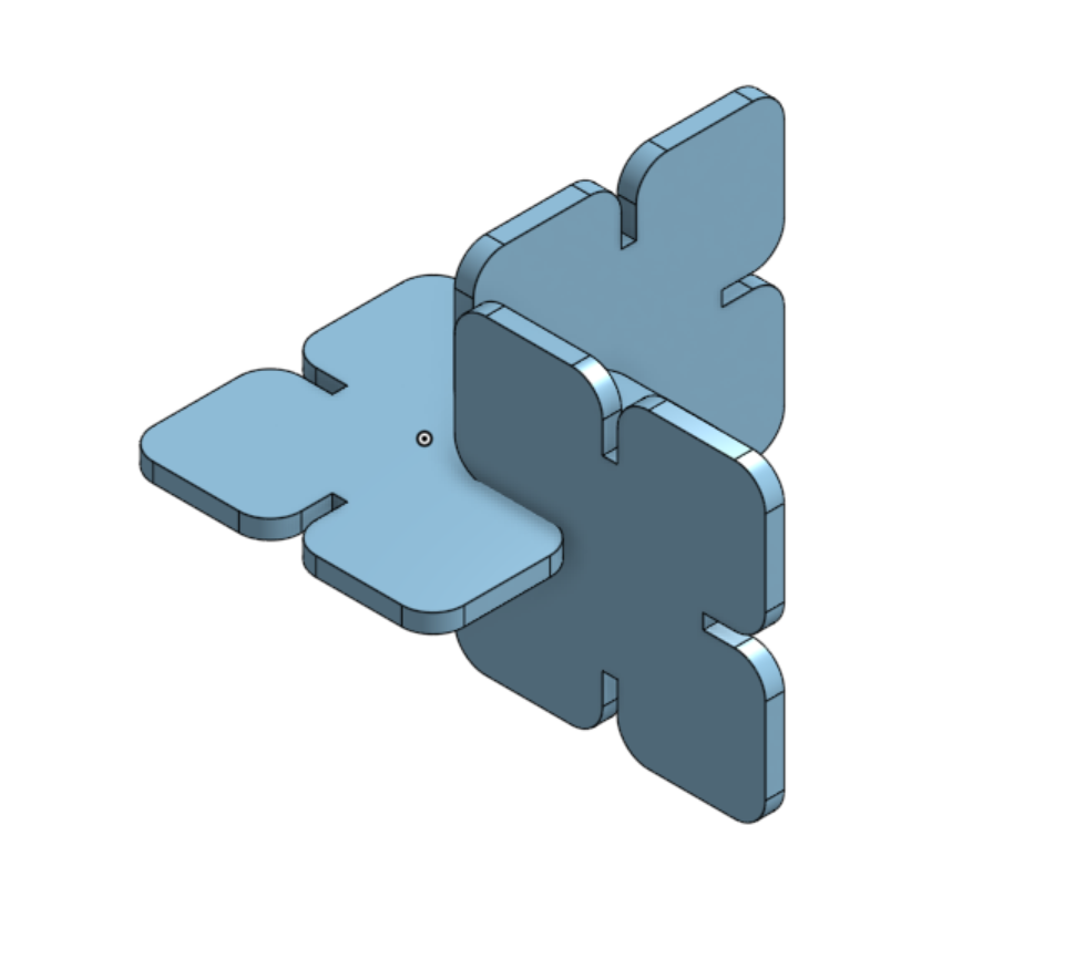
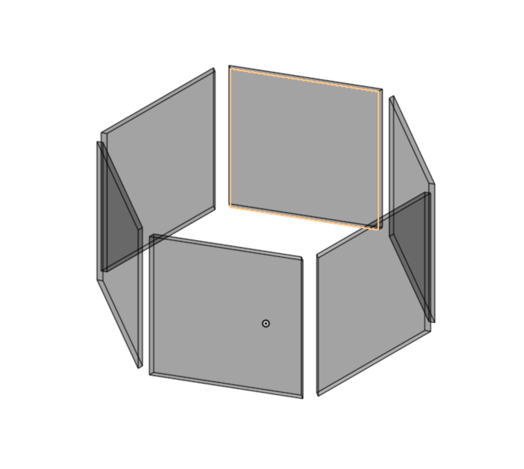
The third piece I modeled was the transparent panels. Using the extrude of the extrude from the dividers, I created a sketch on the surface of the structure of the model to outline the transparent panels.
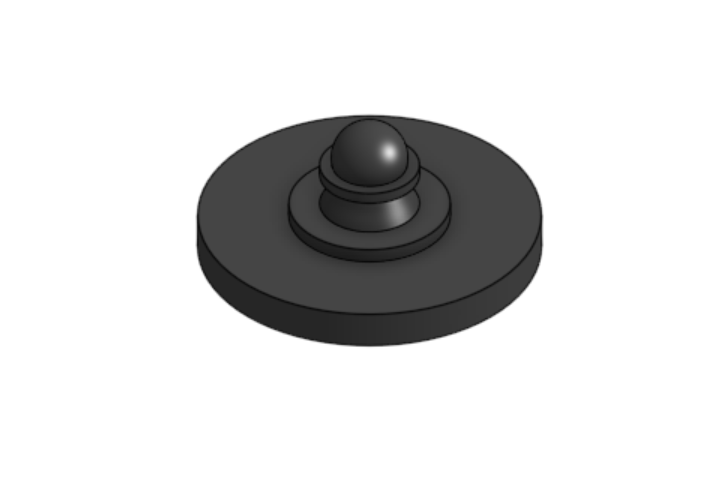
For the final piece, the knob that is used to spin the desktop organizer. I created a sketch ontop of the dividers. I added more cylindrical shapes, a loft and finally a sphere, where the user can put their hand to turn the desktop top organizer.
After all the modeling, I added dark gray and black transparent color to the organizer. Finally, I brought the parts to the assembly, where I attached the base with the structure for the divider with a revolute mate and the panels with the knob onto the previous attachment.