WEEK 7: Electronic Input Devices


During this assignment, there were a couple problems that were quite troublesome being that I couldn't find packet 2 and I got a broken wire stuck in my microcontroller. After a couple hours of trying to debug the problem to no success. I decided to use Tinkercad to test out the input devices.


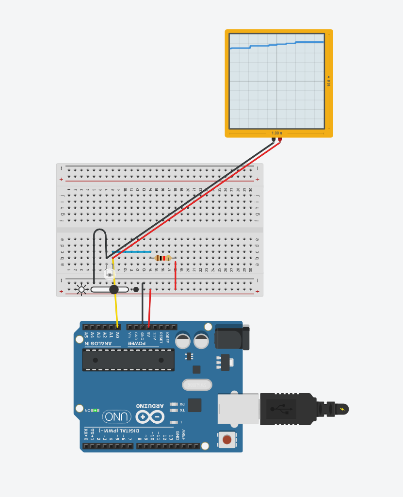
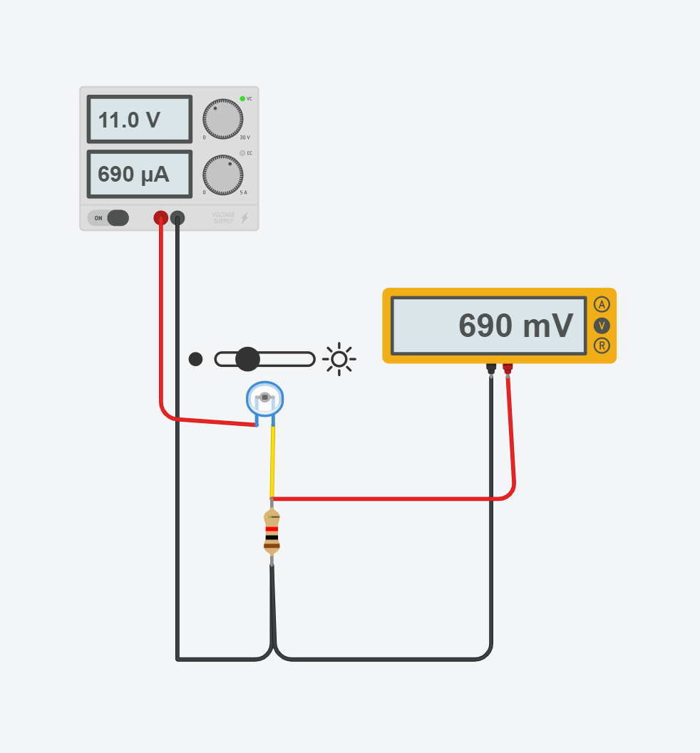
The first input device I tested out was a basic phototransistor circuit, where I would drag a button to increase or decrease the values of the sensor and print out that value. The change in values as I decreased the resistance was mainly linear from 1023 (dark) to 552 (light). When the phototransistor had more resistance it was prone to staying dark with less resistance more bright.

Screenshot of a basic phototransistor circuit

  void setup()
  {
    Serial.begin(9600);
    pinMode(A0, INPUT); // Input pin through A0
  }

  void loop()
  {
    int level = analogRead(A0); // display the phototransistor results
    Serial.println(level);
    delay(100);
  }


Next I tried out the Phototransistor circuit from class and tested out different voltage levels, current and phototransistor values to see how they each affected each other.

Screenshot of a phototransistor circuit that was done in class


I found out that the voltage on the multimeter reflected the amount of current that was stimulating through the circuit, that could only be changed depending on the resistance displayed by the phototransistor.